Notes of a (Java) developer

Unified Modeling Language (category)

Software developer Programmer

Origins

The graphical UML language is generally considered to be standard in the field of software engineering. Its terms (the UML elements) where originally defined in with a reference book by , and . A guide by the same authors defines the way the UML elements should be used. It is important to note that UML is distinct from any software development methodology: the authors introduced in a same time the Unified Process with a third book . The UML language was completely independent from that process.

The OMG

UML evolves nowadays in the frame of the Object Management Group (OMG). The UML is there considered as a component of the Meta Object Facility (MOF). It is a general architecture consisting in four layers. The first one is a metamodel which allows to define the elements of the language (UML) which is the second level. The third layer is the reality being modeled (using the language). At the latest layer comes the object structure.

Using UML ?

In a pragmatic book, considers three ways of using UML:

  • Sketch
  • Blueprint
  • Executable UML

The sketch use of UML is convenient for refactoring programs. Blueprint is in a way the academic use of the language. Finally, Executable UML is a kind of extreme practice of the language in which it becomes the main way of expression for a program.

SysML Callout and UML

Software developer Programmer

Recently, I participated in a Stackoverflow exchange about the SysML Callout concept. The exchange was started in a wrong direction: the initial question was only about the UML language. This was a misconception as the Callout node is a SysML concept and that led to an inappropriate accepted answer which was in fact a non answer.

I write this blog post because I think the topic is an important element in modeling. SysML is a UML profile defined in the frame of the OMG. The SysML 1.3 formal specification poorly defines the term as the effective conceptual definition appears in Annex A, p. 168:

The callout notation provides a mechanism for representing relationships between model elements that appear on different diagram kinds.

Things become more complex to find the proper way to render a Callout. More indications are available in the Allocation section (p. 129):

The allocation relationship can provide an effective means for navigating the model by establishing cross relationships, and ensuring the various parts of the model are properly integrated.

Later (p. 131):

An «allocate» property callout uses the same shorthand notation as the «allocate» property compartment. This notation is also shown in Table 15.1.

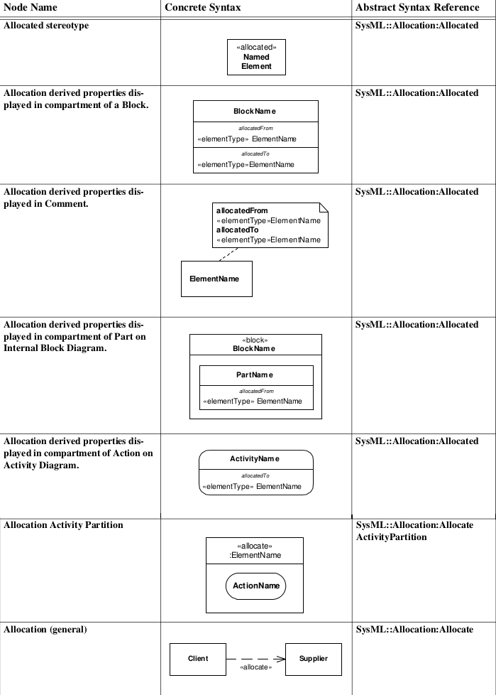
Here is the table explaining the notation of allocations:

In some way, the SysML Callout overlaps the CallBehaviorAction action defined in the UML Superstructure 2.4.1 formal specification, section 1.3.9 on p. 251. This is probably because SysML, as an UML profile, relies on the UML infrastructure.

To be synthetic, relationships between model elements that appear on different diagrams are an important part of modeling. But the representation of a Callout is, in my opinion, not very simple and clear.

STACKOVERFLOW UML SYSML

Web components: adaptation of an XML document

Software developer Programmer

Following my previous post, I tried to play with Polymer on my spare time. In my mind, Web components could be an important point for the architecture of the Web. On one side the Web would be easier to handle for automated systems because of the separation of information and presentation. On the other side Web applications would become easier to design for the same reason.

Software modeling is interesting because it provides a graphical representation of software. As a consequence, UML is an expressive representation for design and documentation. The Eclipse UML2 project relies on an XML file which tends to become a standard form for the persistence of UML models. In that XML file all the informations relative to an UML model are available.

In the discovery of the Polymer platform came the idea of Polymeria: bridging the gap between the XML representation of an UML model and its graphical representation. The principle sounds simple: writing a Web component for each UML element. This is an echo to the idea exposed by E. Bidelman that every framework is compatible with DOM (further information is available in my previous post).

First constraint: Web component names must contain a dash in order to avoid overriding standard HTML element names. The problem is that Eclipse UML2 XML element names do not necessarily contain a dash. In other words, the XML file needs a transformation.

The main issue comes with the Web component for an UML attribute: the XML tag generated by most UML2 tools is self-closing. The behavior is quite surprising in some cases, some side-effects are completely unexpected. For example, some classes appear in a wrong package. I open an issue in the Polymer project because the self-closing tag renders in a surprising way. And it appears one and two others had been submitted before. Self-closing tags are not allowed in Web components.

Every framework is compatible with DOM. But DOM is not necessarily compatible with Web components. After these two limitations, it seems Web components are perhaps XML compliant. However an XML model is tricky to adapt as a Web components document. The random support of self-closing tags can be rather disappointing for a first contact with Web components...

Here is an HTML sample of Polymeria showing the transformations needed and the Web components obtained (a proper rendering has been tested with Chrome and Firefox).

WEB WEB COMPONENTS W3C POLYMER UML

Point of view: Packaging

Software developer Programmer

According to The Unified Modeling Language User Guide, object-oriented software elements belong to one of these four categories:

  • Structural things
  • Behavioral things
  • Grouping things
  • Notational things

Obviously, classes are structural elements. According to this same book, packaging is the act of grouping classes.

Something is bothering me about packaging. All programs I have been working on, and all courses I have been following, share a single vision of the way these groups should be considered.

In this single vision, classes are grouped on structural criteria. In a same package, we will find objects assuming a single role: DAOs with DAOs, entities with entities, controllers with controllers. To be honest, this helps designing interesting class diagrams. This has a real interest for building effective heritage hierarchies.

But in my point of view, we let apart behavioral criteria. One DAO object usually interacts only with a single entity class and a few services. This means, if we design sequence, activity or state diagrams, the involved objects will belong to different packages. This would be very helpful to help software maintenance: in a single set we have all the relevant elements.

Here is a summary:
  1. Usually, package elements grouping is based on classes roles to help software design
  2. Package elements grouping should also be based on classes interactions to help software maintenance

If we would like to design really modular applications, I think we should consider these two axes while packaging. On a pure design point of view, a class should belong to two packages : one structural (1) and one behavioral (2). This could be possible because one class usually has interactions with a few classes.

In Java, one solution to help set up this second kind of packages could be annotations. But the problem would be in class loading. This wouldn't be a real problem if we all time use to write APIs.

A pragmatic solution would be to change the packaging in the development process. Once the software has been designed building interesting heritage hierarchies based on roles, packaging should be modified to follow classes interactions in order to help software maintenance.

Heisenbug - Concurrency case

Software developer Programmer

Solving an Heisenbug can be really tricky. This kind of bug occurs when the program execution conditions are changing. In many cases, using a debugger or a log output doesn't help. Such tools can have an influence on the execution.

I once faced such a bug in a Swing application. The problem occurred in a quite long process (half an hour)  at various steps with constant input data. I lost time with that bug because I had no methodology. I have to admit the final solution was rather simple.

I designed an activity diagram of the main activities involved in the failing process. I paid attention to swimlanes because I suspected a concurrency problem. For each activity there was a single log output. A custom logging level was set up so that only activity logs could be written (an attempt with the debug log level was completely helpless). The logging framework was also configured to print the current thread name. There I got the activity which was not in the right place and the name of the criminal. The random occurrence of the problem was probably due to the variable system load and user interactions.